Analysis of Regenerative Braking and Its Dependence on Electric Motor Types in EV Powertrains
Overview: Regenerative braking is a key technology in hybrid and electric vehicles (EVs) that recovers kinetic energy during deceleration by running the traction motor as a generator. This recovered energy, which would otherwise be wasted as heat in friction brakes, is stored in the vehicle’s battery or capacitor for later use. The fundamental principle relies on electromagnetic induction – as a motor’s rotor continues to spin faster than the magnetic field it creates (or is forced to spin), it generates an opposing electromotive force (back-EMF) that can drive current back into the energy storage system. In effect, the motor–inverter acts as a generator during braking. Regenerative braking can significantly improve vehicle energy efficiency (recovering a substantial fraction of braking energy) and reduce mechanical brake wear. However, its performance and characteristics depend heavily on the type of electric motor used, the power electronics and control strategy, and system constraints such as battery state-of-charge (SOC) and low-speed limits.
Key Points: Below we examine the physics of electromagnetic induction in motors, how back-EMF enables energy recovery, and how motor characteristics (e.g. permanent-magnet synchronous vs. induction vs. switched-reluctance) affect regenerative braking. We review motor control techniques (field-oriented control, vector control, flux weakening), compare motor types in terms of torque density and regen efficiency, and discuss how major automakers implement regeneration. Practical limits (battery SOC, low-speed regeneration, stability, comfort) and blended braking (integration with friction brakes) are analyzed. Case studies and data from production EVs illustrate real-world regen performance. Finally, we explore environmental and economic impacts, recent research in motor/inverter design to enhance regen, and future trends in integrated motor-inverter-battery systems.
Fundamentals of Regenerative Braking

Regenerative braking is an energy-recovery mechanism: during deceleration, the vehicle’s kinetic energy is converted into electrical energy by the motor-generator and stored, rather than dissipating it as heat in mechanical brakes. In practice, the traction motor (or generator in a hybrid) is driven into its generating mode by commanding a negative torque that opposes wheel rotation. When the driver lifts off the accelerator (or applies the brake pedal), the motor controller reduces or reverses the motor torque. As the wheels turn the motor shaft, the rotor’s motion through the stator magnetic field induces an EMF (per Faraday’s Law), causing current to flow back to the battery. The result is that some fraction of the vehicle’s kinetic energy is recaptured and stored, improving overall efficiency.
Electromagnetically, Faraday’s Law states that a time-varying magnetic flux through a coil induces an EMF:
where is the number of turns and the magnetic flux. In a rotating electric machine, when the rotor is turned faster than its synchronous field (or, equivalently, forced above the frequency imposed by the inverter), the change in flux linkage induces a back-EMF consistent with Faraday’s Law. Lenz’s Law further dictates that this induced EMF opposes the change, i.e. it produces a torque that resists the motion (braking the rotor). Thus, the motor effectively behaves as a generator, converting mechanical input (from the wheels) into electrical output (into the battery).
At steady state, the induced EMF in a motor is proportional to its mechanical angular velocity . In a simple DC or brushless motor model, the back-EMF can be written as , where is a motor constant related to flux. Correspondingly, the torque developed by the motor (or generator) is proportional to the current : . In ideal electromechanical devices in SI units, . Hence, as the motor/generator spins, a voltage builds up that is proportional to speed, and the current drawn (or pushed) is proportional to torque. Power output is .
Figure: Torque–velocity quadrants illustrating motoring (drive) vs. regenerative braking. In motoring (Q1) the motor provides positive torque and positive speed; in regeneration (Q2) the motor provides negative (braking) torque while the vehicle speed is still positive. The shaded blue car in Q2 is driving downhill and the motor acts as a generator.
The simple quadrant diagram above illustrates the energy flow concept. In the upper-right quadrant (positive torque, positive velocity), the vehicle is accelerating under motor power (energy flows from battery→motor→wheels). In the lower-right quadrant (positive velocity, negative torque), the vehicle is coasting or braking. If we command negative motor torque (braking torque), and the wheels continue to turn, the machine enters its generating region: mechanical energy (from inertia) is fed back into the electrical system (energy flows from wheels→motor→battery). In practice, only part of this braking energy is captured (the rest must be handled by friction brakes), and the actual recovered power is limited by factors such as the battery’s charging power limit, the inverter rating, and the minimum speed for generation.
Energy Flow During Acceleration and Braking
During normal acceleration, energy flows from the battery through the inverter into the motor, generating mechanical torque at the wheels. In regenerative braking, the flow reverses: the wheels turn the motor, and electrical power flows backward through the inverter into the battery. A conceptual energy flow diagram is:
-
Acceleration (motoring): Battery → Inverter/Motor → Wheels → Vehicle kinetic energy.
-
Regenerative braking: Wheels (kinetic) → Motor (generator) → Inverter → Battery.
The recovered electrical energy is measured at the generator output and compared to the consumed energy at the motor input. Efficiency of conversion () is typically less than 100% due to losses in copper resistances, core losses, inverter switching losses, and battery charge acceptance. Control strategies (e.g. limiting torque to avoid wheel slip, gradually blending friction brakes, managing battery current) play a major role in how much energy is actually recaptured.
Faraday’s law underpins this process: as the rotor cuts the magnetic field lines, an EMF is induced that opposes the motion. This back-EMF grows with rotor speed: “Back emf is zero when the motor is not turning and increases proportionally to the motor’s angular velocity”. When braking, the motor controller reduces the inverter’s output frequency (and voltage) so that the motor is driven above its synchronous speed, forcing the slip negative (in an induction motor) or directly producing negative torque (in a synchronous motor). When the induced EMF exceeds the battery voltage, current is pushed into the battery, and braking torque is produced. The controller must monitor battery voltage to ensure safe charging; if the battery cannot accept more current (e.g. at high SOC), regen torque is limited and additional braking is done mechanically.
Electric Motor Types and Regenerative Braking
EVs and hybrids use various motor types, each with its own characteristics affecting regenerative braking. The principal types are:
-
Permanent Magnet Synchronous Motor (PMSM) – A synchronous AC motor with permanent magnets on the rotor.
-
Brushless DC Motor (BLDC) – An electronically commutated motor with permanent magnets, typically trapezoidal back-EMF; often treated similarly to PMSM.
-
Induction Motor (IM) – An asynchronous AC motor (squirrel-cage rotor).
-
Switched Reluctance Motor (SRM) – A motor with a simple salient-pole stator and no windings or magnets on the rotor; torque arises from reluctance.
-
Wound-Rotor Synchronous Motor (WRSM) – A synchronous motor with rotor windings (fed through slip rings).
We now discuss each motor type’s operating principle, how regeneration works, and their implications for torque, efficiency, and control. A comparative table later summarizes key parameters.
Permanent Magnet Synchronous Motors (PMSM)
Principle: A PMSM has permanent magnets embedded or mounted on the rotor; the stator carries a three-phase winding. When driven by AC currents, a rotating magnetic field is set up in the stator. The rotor’s permanent-magnet flux locks in sync with the stator field, hence “synchronous motor.” The motor’s torque is typically sinusoidally produced and controlled by a vector (field-oriented) algorithm. Modern EV PMSMs use interior permanent magnets (IPMSM) to allow field weakening at high speed.

Regenerative Operation: In motoring mode, the inverter supplies currents to produce torque in the forward direction. In regen mode, the motor is driven to produce negative torque (i.e. oppose rotation). Because the rotor is synchronous, to get negative torque, the controller commands currents that lag (are 180° out of phase) with the rotor flux, effectively driving the motor backward. When rotor speed exceeds the stator’s synchronous speed (or equivalently, the electrical frequency is reduced below the mechanical frequency), the machine generates power. PMSMs can generate power at low speeds as well as high speeds (down to zero speed theoretically) as long as the inverter can commutate and the back-EMF reaches the battery voltage. In practice, very low-speed regeneration is often limited by control or inverter constraints.
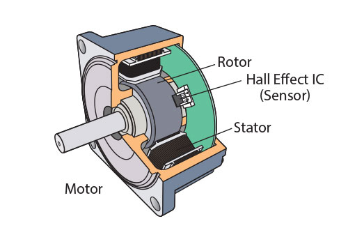
Characteristics: PMSMs have very high torque density and efficiency, because their magnetic field is strong and stable (no rotor losses). They typically offer high regen efficiency and can deliver strong braking torque. Downsides include the use of costly rare-earth magnets, which adds expense and concerns about demagnetization at high temperatures. PMSMs require precise rotor position sensing (hall sensors or encoders) and a full FOC control strategy. Field-weakening control (applying a negative d-axis current) is often used to allow high-speed operation beyond base speed.
Real-world Use: Many modern EVs use PMSMs. For example, Tesla’s Model 3 uses a high-performance PMSM (especially in the rear motor for the Long Range version). The Hyundai Ioniq Electric and Kona Electric also use PMSMs. In hybrids, Toyota’s traction motors are synchronous (with permanent magnets). BLDC motors are often grouped with PMSMs, since a “BLDC motor” in automotive use is generally a synchronous PM machine with trapezoidal back-EMF, controlled in a similar way.
Brushless DC Motors (BLDC)
Principle: A BLDC motor is essentially a synchronous motor with permanent magnets on the rotor, but with a stator winding and electronics that produce a roughly trapezoidal back-EMF waveform. Unlike PMSMs (which ideally have sinusoidal current commutation), BLDCs can be commutated with simpler “six-step” control aligning stator phases to the trapezoidal rotor back-EMF. In theory, BLDC and PMSM are very similar; the main difference is waveform shape (square-wave vs sinusoidal current).
Regenerative Operation: BLDCs also readily support regeneration. When decelerating, the drive electronics simply commutate the stator currents to produce negative torque (opposing rotation), just as with a PMSM. In effect, the BLDC’s permanent magnets ensure that any rotor movement induces a voltage, which can feed the battery. The difference from PMSM is subtle: BLDC controllers often include anti-cogging functions and might handle current differently, but the physical regen process is analogous.
Characteristics: BLDC motors share the high efficiency and torque density of PMSMs (they use similar magnets). They are costlier due to magnets, and typically have similar control complexity. Because of the simpler commutation (six-step), BLDC controllers may have slightly different switching losses, but regen efficiency is still high. In practice, many so-called “BLDC” automotive motors are simply controlled as PMSMs using FOC, which blends the lines between BLDC and PMSM operation.
Real-world Use: Many early EV and hybrid motors are described as BLDC (e.g. bicycle hub motors, Prius hybrid motor/generators). Modern automotive BLDC/PMSM drives are ubiquitous in EVs and e-bikes.
Induction Motors (IM)
Principle: An induction (asynchronous) motor has a stator similar to the above, but its rotor is a simple “squirrel-cage” of conductive bars with no magnets. The stator’s rotating magnetic field induces currents in the rotor bars; these rotor currents produce their own magnetic field which interacts with the stator field to generate torque. The rotor always lags the stator field in speed (hence “slip”); the motor only produces torque when the rotor speed is below synchronous.
Regenerative Operation: An induction motor can regenerate, but the mechanism is different. For regen, the rotor must turn faster than the synchronous speed of the stator field. This reverses the power flow: the rotor’s inertia causes current to be induced in the cage that generates torque opposite to the motion. In practice, the inverter/drive commands a lower frequency than the actual mechanical speed, so from the drive’s perspective the motor is overspeeding. The negative slip causes the stator currents to deliver energy back through the inverter to the battery. Thus, regen in an IM requires controller action to produce the condition (rotor > synchronous) for the motor to act as a generator.

Characteristics: Induction motors are robust and inexpensive (no magnets, just cast copper/aluminum rotor). However, they suffer rotor copper losses when spinning, which reduces regen efficiency (some mechanical energy is lost as heat in the rotor bars during regeneration). Their torque density is generally lower than a PMSM of the same size because they rely on induced fields (though modern designs mitigate this). Control requires FOC (sensorless or with sensors) to manage slip precisely for regen and motoring. Induction machines typically have poorer low-speed torque than PMSM unless flux-concentration techniques are used, meaning regen at very low speeds can be weak.
Real-world Use: Tesla famously used 3-phase induction motors in the Model S and Model X (13" and 17" motors) for their reliability and high-speed capability. The induction motor allowed regenerative braking but required sophisticated control. Tesla’s Model 3 LR and P100D use a combination of PMSM (rear) and induction (front) for AWD: this hybrid approach leverages the strengths of both. Other manufacturers (like Jaguar i-Pace) use induction motors as well.
Switched Reluctance Motors (SRM)
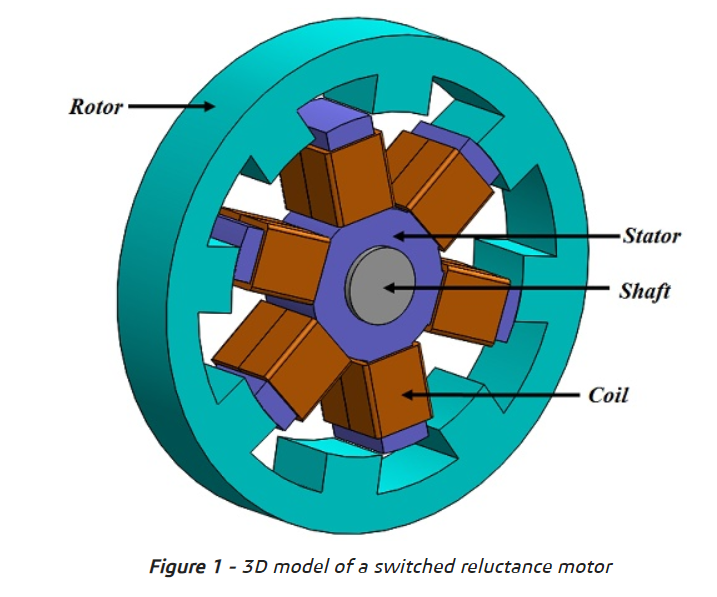
Principle: An SRM has a very simple construction: a stator with windings on salient poles, and a rotor of ferromagnetic poles with no coils or magnets. Torque arises from the tendency of the rotor to move to a position of minimum reluctance (aligning its poles with the energized stator poles). Commutation is achieved by switching current through the stator phases as the rotor moves, typically using specialized control.
Regenerative Operation: An SRM can also function as a generator. During motoring, stator currents are sequentially energized to pull the rotor along. For regeneration, the controller times the currents so that the rotor’s motion induces a voltage in the stator winding that is of opposite polarity to the applied current. Effectively, the rotor wants to move out of phase with the energized stator field. This requires precise control of switching. In practice, if the rotor is being driven faster than the commanded stator sequence (or if the stator phases are de-energized at the correct times), current will flow out of the stator back through the inverter to the battery, generating braking torque.
Characteristics: SRMs are very simple and robust (no magnets, rugged rotor, can tolerate high temperatures). They have high torque density and can handle high speeds. However, they suffer from torque ripple and require very complex control algorithms (often in real-time) to manage current timing and smooth torque. Their efficiency in both motoring and regeneration is typically lower than PMSMs because of rapid current switching and magnetic losses due to the reluc- tance changes. As a result, regen efficiency is generally worse than PMSM/BLDC. Also, since there are no magnets, there is no permanent flux; all flux must be generated by current, so high current is needed for strong torque. Regeneration in SRM often yields pulsed or bumpy torque without careful control.
Real-world Use: SRMs have been explored in EV contexts but are not yet common in production vehicles. Research shows PMSM drives outperform SRMs in EV applications requiring high torque and power density. Nissan built an experimental SRM-powered EV (the “Machina” concept) and used an SRM in their 2017 Formula E racecar, demonstrating the concept but also the control challenges. Major OEMs have not yet adopted SRM for mainstream EVs, though interest remains due to low cost and robustness.
Wound-Rotor Synchronous Motors (WRSM)
Principle: A WRSM is a synchronous AC motor similar to a PMSM, except that the rotor has windings (connected via slip rings or a rotating transformer) that are excited with DC to create the rotor field. In effect, the rotor acts like an electromagnet rather than permanent magnets.
Regenerative Operation: Because the motor’s rotor field is excited by controllable DC current, a WRSM can regenerate similarly to a PMSM. When the motor is driven as a generator (by commanding negative torque), the generated AC is converted to DC by the inverter and fed back. The difference is that rotor excitation can be adjusted: for example, one could reduce the rotor current to facilitate field weakening at high speed or to shape the regeneration torque. The regen action is synchronous: as with PMSM, negative torque occurs if the electrical supply is driven “backwards” relative to rotor position.
Characteristics: WRSMs do not require permanent magnets (so magnet cost is avoided) but do require slip rings or other means to feed the rotor DC current, adding mechanical complexity and maintenance. Their torque density and efficiency are generally moderate. The ability to adjust rotor excitation means they can potentially do more field weakening or even “field boosting” if needed, giving flexibility in speed range. However, the slip-ring assembly adds cost and complexity.
Real-world Use: WRSMs are not commonly used in passenger EVs due to the complexity of slip rings and brush gear. They are more often found in industrial or marine applications. In principle a WRSM in an EV would allow regeneration, but typically any performance advantages are offset by the mechanical drawbacks. Some specialized EVs (e.g. locomotives) use variations of wound-field machines for similar reasons.
Comparison of Motor Types
The table below summarizes key attributes of these motor types in the context of EV regenerative braking:
| Motor Type | Torque Density | Regenerative Efficiency | Cost | Control Complexity | Example Applications |
|---|---|---|---|---|---|
| PMSM | Very High (best) | High (efficient) | High (rare-earth magnets) | Moderate (requires sensors + FOC) | Tesla Model 3 (rear), Hyundai Kona Electric, BMW i3 |
| BLDC | High (≈PMSM) | High (similar to PMSM) | High (magnets) | Moderate (six-step or FOC) | Early Prius MG2, EV scooters, e-bikes |
| Induction Motor | Moderate | Moderate (rotor losses) | Low | Moderate (FOC with slip estimation) | Tesla Model S/X, Jaguar I-Pace |
| Switched Reluctance Motor (SRM) | High (comparable to PMSM) | Lower (ripple + switching losses) | Low | High (complex current switching) | Experimental EVs (Nissan Machina), some e-trikes |
| Wound-Rotor Synchronous (WRSM) | Moderate | Moderate (≈PMSM with adjustability) | High (rotor excitation + slip rings) | High (excitation control + sensors) | Niche/heavy-duty (e.g. large EV buses, marine) |
Table: Comparison of EV motor types. “Torque density” reflects torque per unit volume; “regen efficiency” indicates how effectively mechanical energy is converted to electrical under braking; cost and complexity are relative. (Sources: motor reference texts, practical EV knowledge.)
-
Torque Density: PMSM and BLDC lead with the highest torque output for a given size. SRM can also produce high torque for short bursts (due to robust magnetic circuits), but usually less continuously. Induction motors have somewhat lower torque density because they rely on induced fields. WRSM torque density is moderate.
-
Regenerative Efficiency: Permanent-magnet motors (PMSM/BLDC) have the highest regeneration efficiency, as there are no rotor copper losses; most losses are in the inverter and stator resistance. Induction motors incur rotor I²R losses during regen. SRMs suffer core and switching losses that reduce regen efficiency. WRSM efficiency is similar to PMSM if excitation is optimal, though slip-ring losses can appear.
-
Cost: Induction and SRM are cheaper (no expensive magnets). PMSM/BLDC and WRSM are costly due to magnets or rotor windings.
-
Control: All AC types need FOC vector control. SRM and WRSM often need even more complex control (adaptive timing, excitation control). BLDC sometimes uses simpler commutation (six-step), but high-performance EV drives generally use FOC for smoother torque.
Motor Control Strategies
Efficient regenerative braking relies on advanced motor control. The most common approach is Field-Oriented Control (FOC), also known as vector control. FOC decouples torque and flux control by transforming currents into the rotor reference frame (d, q axes). A typical FOC architecture (for a PMSM) is shown below:
Figure: Block diagram of a typical Field-Oriented Control (FOC) system for a synchronous motor. The controller generates d,q current references (id_ref, iq_ref), which are transformed (Park/Clarke) into three-phase voltages via a space-vector PWM (SVPWM) inverter to drive the motor. An outer velocity loop provides torque commands, while protection/auxiliary functions manage limits.
In FOC, an outer loop (often a speed or torque controller) determines the reference currents (flux-producing) and (torque-producing). During normal motoring, yields positive torque. For regenerative braking, the control simply targets a negative (or equivalently reverses the torque command). The inverter then produces AC waveforms that cause the motor to generate power back to the DC link. The FOC scheme can smoothly adjust braking torque as needed.
Vector Control / Direct Torque Control: Another approach is Direct Torque Control (DTC), which directly manipulates inverter switching to maintain torque and flux. DTC can also achieve regeneration by commanding the torque below zero. Modern EVs overwhelmingly use FOC or DTC to handle both motoring and regenerating seamlessly.
Flux Weakening: Field-weakening (flux-weakening) control is used when speeds exceed the motor’s base speed. By injecting a negative d-axis current () in a PMSM or WRSM, the net air-gap flux is reduced, allowing the motor to run at higher speeds under a limited voltage. Flux weakening reduces the motor’s torque constant but prevents the back-EMF from exceeding the inverter voltage. This technique is also relevant in regen mode: to sustain braking at high speeds, the controller must manage field weakening. Interior magnet motors (IPM) are designed to accommodate field weakening efficiently. The MathWorks documentation notes that for speeds above rated, FOC with field-weakening is used.
Sensor and Sensorless Control: Position sensing (via encoders or resolvers) is typically used for precise FOC. Sensorless methods estimate rotor position from voltage/current measurements, but accurate low-speed control (including regeneration from standstill) can be challenging without sensors. Many EV controllers use rotor encoders for reliability.
Blending with Vehicle Controls: The braking system’s ECU or brake controller must coordinate regen torque with friction brakes. It monitors wheel speeds (via ABS sensors) and driver input, and decides how much torque to allocate to the electric motor vs hydraulic brakes. Regenerative control logic often takes into account wheel slip to prevent locking, seamlessly handing off to friction brakes when limits are reached.
Historical Evolution of Regenerative Braking
Regenerative braking has roots early in the automotive timeline. Even late-19th and early-20th-century electric vehicles and trams had primitive regen systems. For example, the Baker Electric Runabout (1915) and the Owen Magnetic car (1930s) featured regenerative drives, though they required drivers to manually switch modes. The concept faded as efficient mechanical brakes dominated until the mid-late 20th century, when hybrid and electric vehicles revived it.
-
1970s-80s: Early research into regenerative systems appeared, but mainstream adoption waited for solid-state electronics. NASA’s lunar rover (1971) recovered energy from its wheels during descent.
-
1990s: Hybrid vehicles (e.g. Honda Insight 1999, Toyota Prius 1997 in Japan) brought regen to mass markets. The Toyota Prius hybrid synergistically used two motor-generators: one as a starter and one for traction/regeneration.
-
2000s-Present: Plug-in hybrids and battery EVs commonly include regen. By the 2010s, OEMs from Toyota to Tesla were integrating regen with advanced controls (e.g. “one-pedal driving” modes). Modern EVs routinely achieve high regen rates (often recouping a quarter or more of braking energy in real driving).
The historical trend shows growing sophistication: from manual switching to fully integrated ECU-managed regen. Early hybrids like the Gen1 Prius could only regenerate modest power due to NiMH battery limits, while today’s Li-ion EVs capture much more energy thanks to higher battery power capacity. Research and patents (e.g. by Tesla, Toyota, Bosch) over the last two decades reflect continuous innovation in regen algorithms, braking blending, and energy management.
Regenerative Braking in Production EVs (Manufacturer Comparisons)
Different automakers implement regenerative braking in ways that reflect their drivetrain designs and control philosophies. Here are a few examples:
-
Tesla (Model S/3/X): Early Model S/X used 3-phase induction motors. Tesla’s controllers allow “one-pedal driving”, where lifting off the accelerator engages strong regen, decelerating the car significantly without the brake pedal. Tesla quotes up to ~70% energy recovery under ideal conditions, though real-world rates are often lower. In practice, a Tesla Model S can decelerate from highway speed primarily by regen, reserving friction brakes for very low speeds or emergencies. Tesla’s dual-motor AWD versions use a PMSM in one axle and an induction in the other, coordinating regen between them. The heavy use of regen on Teslas means drivers often rarely use the brake pedal in normal driving, which also reduces brake wear.
-
Nissan (Leaf): The Nissan Leaf uses an AC synchronous motor (PMSM) paired with a 6-speed shift-by-wire and e-Pedal regen mode. Its regen efficiency is typically high (since there are no rotor losses). Nissan claims about 39% of kinetic energy can be recovered in braking. The Leaf allows two levels of one-pedal regen: “B” mode (brake) and “ECO” mode for lighter regen. Many Leaf drivers observe roughly 20-30% improvement in range in city driving via rege
-
Toyota (Prius Hybrids): Toyota’s hybrid motor-generators are synchronous (MG2 is 3-phase AC, likely permanent-magnet, though sometimes loosely called BLDC). Regeneration is integrated with engine braking: the system will regenerate up to a certain power (about 23 kW in Gen3 NiMH Prius). Because NiMH batteries cannot charge extremely quickly, Toyota blended regen carefully – when battery SOC is high, less regen goes to the battery and more friction braking is used. The Prius normally uses friction braking below about 20–25 km/h (or when SOC is full). Toyota’s control logic also aims for smoothness, limiting jerk. One review noted Prius regen is “second to none” among hybrids for smoothness, engaging regen gently to avoid passenger discomfort.
-
Hyundai/Kia: Modern Hyundai/Kia EVs (e.g. Kona Electric, Ioniq 5) use permanent-magnet motors with strong regen. They offer multiple regen levels via paddle shifters, and an “Eco” mode that coasts less and regenerates more. During regen, some series manage battery current carefully to optimize energy recovery. If the battery is full, regen is curtailed. Regeneration in these vehicles can be very aggressive (sometimes capturing 60-70% of energy in test cycles), contributing to their high efficiency ratings.
-
BMW (i3): The BMW i3 electric uses a PMSM with an 1-speed reducer. BMW’s regen strategy allows very strong deceleration (similar to one-pedal feel). The i3’s controller also manages friction brakes for safety. Its regen captures around 50–60% of braking energy in urban driving according to some tests. BMW incorporates an “Adaptive Regeneration” system that adjusts regen based on navigation (e.g. regen more when approaching an intersection or downhill).
-
Others: Most other EVs (Chevrolet Bolt, VW e-Golf, Tesla Model Y, Lucid Air, Rivian) use similar approaches with PMSM drives. Commercial EVs and buses often use induction or synchronous induction drives; regen in those applications must also account for heavy vehicle dynamics. Formula 1 hybrids (Hybrid ERS systems) use sophisticated regen (KERS) but are beyond this overview.


Each manufacturer tunes regen differently. Factors include: motor type, battery chemistry (Li-ion vs NiMH), vehicle dynamics, and user interface. Some cars allow “blended” braking where the brake pedal gradually applies friction brakes as regen saturates; others let the driver rely entirely on the accelerator pedal to modulate regen.
Integration of Regenerative and Friction Braking (Blended Braking)
A key aspect of regenerative braking systems is blending with traditional friction brakes to achieve safe, smooth deceleration under all conditions. Since electric regeneration cannot always absorb all kinetic energy (due to battery limits, motor speed, or traction slip), the braking system must seamlessly combine regenerative and hydraulic braking.
-
Brake Controller: Modern EV brake controllers monitor wheel speed and slip (via ABS sensors) along with driver brake pedal input. If regen is insufficient to provide the requested deceleration (e.g. at very low speeds or full battery), the controller proportionally engages friction brakes. Conversely, if regen alone can meet the deceleration, the friction system may remain idle, saving brake wear. The transition is smooth: some systems never let the friction brakes activate until regen is exhausted, whereas others modulate both in parallel for pedal feel.
-
Safety and ABS: Regen must play nicely with anti-lock braking systems (ABS). ABS needs to prevent wheel lockup even under regen torque. Vehicles ensure regen torque is modulated by slip algorithms just as friction brakes would. If sudden regen torque causes too much deceleration, ABS can cut regen momentarily or apply friction.
-
User Experience: Manufacturers often calibrate regen so that an “even” pedal feel is achieved. In many designs, the brake pedal first engages regen before the hydraulic system engages, making one-pedal driving possible. However, this can feel different from a conventional car. To ensure safety, all vehicles allow the driver to override regen by firmly pressing the brake pedal (some high regen cars even fully disable regen when braking very hard).
-
Control Strategy: The reference driver typically touches are mapped to a desired deceleration rate. The controller then commands regen torque up to a limit (battery charge current, motor power) and uses friction brake filling as needed. As one technical source notes, “power reception from braking is limited by generator power, minimum speed, or battery capacity. The part of energy not used for regenerative braking is transferred to the regular braking system”.
In summary, blended braking ensures safety and consistency: the electric motor provides braking force as much as possible (up to limits) and mechanical brakes make up the remainder. This integration is managed in real time by the vehicle’s brake/ABS controller, often making the transition imperceptible to the driver.
Practical Limits and Challenges
While regenerative braking is beneficial, several practical limits and challenges arise:
-
Battery State-of-Charge (SOC): The battery can only accept a certain charge power. If SOC is near full (especially in hybrids with small batteries or EVs leaving charge pending for engine charging), regen must be reduced. Some vehicles incorporate a passive resistor load or auxiliary systems to dump excess energy if needed, but typically regen is simply cut off and friction brakes handle the rest. Thus, regen efficiency drops at high SOC.
-
Minimum Speed: Many motors/inverters have a minimum practical speed for generating. Below a threshold (often a few km/h), there isn’t enough back-EMF to feed the battery. Consequently, regen virtually vanishes at very low speeds (typically below ~5–10 km/h), so stopping from crawl is done by mechanical brakes alone. This is why even “one-pedal” cars click into friction braking near zero speed.
-
Torque Slip and Traction: Regenerative braking can lock wheels if the torque is too high for road friction (especially on slippery surfaces). ABS/traction controls must modulate regen to avoid skids. Some systems temporarily disable regen if a skid is detected, as friction brakes can be more easily pulsed by ABS.
-
Ride Comfort and Control: Aggressive regen can cause jerking deceleration. Manufacturers calibrate the regen torque to match driver expectations and mechanical brake feel. They also limit how quickly regen torque can change (jerk control) to maintain comfort. As one study notes, combining regen control with adhesion management can keep driver “jerk” low (<3 m/s³) while improving energy recovery.
-
Thermal Limits: During prolonged heavy regeneration (e.g. long downhill), the motor/inverter or battery could overheat. Systems may throttle regen to prevent excessive current and temperature. This can be an issue for high-power regen requests.
-
Incomplete Energy Recovery: Not all kinetic energy can be captured. Typical round-trip energy efficiency for regen (mechanical→electrical→mechanical reuse) is in the range of 60–70%, meaning 30–40% is still lost to heat and conversions. Real-world studies suggest that urban driving can recapture ~20-30% of total energy usage via regen (since not all brake events can be fed back). One source indicated urban regen “yielded about 8–25% fuel economy improvement”.
-
System Complexity: Adding regen requires power electronics capable of four-quadrant operation (driving and generating), a robust battery management system, and sophisticated software. This adds cost and design complexity compared to a friction-only system.
Despite these challenges, careful design and control allow modern EVs to make extensive use of regenerative braking under normal conditions. For example, tests show that in a typical urban route, an EV may see on the order of 20–40% of its kinetic energy recovered, depending on drive style and conditions.
Real-World Performance Data and Case Studies
Performance data on regen varies by vehicle and driving cycle. Some representative figures:
-
A Smart EQ urban EV and a Mazda MX-30 tested under city conditions showed notable regen potential in stop-go traffic. In experimental routes, authors noted that the fraction of distance covered under regenerative braking mode was significant.
-
In one study, a Nissan Leaf owner reported recovering on the order of 500 Wh over a 25-mile drive (~10% of total energy consumption) through regular driving and braking.
-
Tesla claims its regen can recapture up to 70% of kinetic energy in braking, though others measure around 60% in aggressive one-pedal mode. (This depends on speed, battery, etc.)
-
For a Toyota Prius hybrid, regen energy is lower due to NiMH limits; roughly 20–30% of braking energy is typically recaptured (the rest being dissipated in engine and mechanical brakes).
Overall, EV manufacturers often quote range gains of 10–20% from regen in mixed driving. Brake component lifetimes are also significantly extended: some studies cite that EVs may hardly need brake pad changes for tens of thousands of kilometers. In London Underground trains, which use regen when feeding the third rail, about 20% of energy usage is saved via regen.
Environmental and Economic Impact
Regenerative braking improves energy efficiency, which has both environmental and economic benefits. By recapturing energy that would otherwise be wasted, it extends EV driving range and reduces electricity/fuel consumption. For example, recapturing 30% of braking energy could translate to a similar increase in range or equivalent fuel savings in a hybrid mode.
Emissions: In hybrids, more regen means less reliance on the engine for braking and acceleration energy, reducing fuel burn and emissions during city driving (where braking is frequent). EVs produce no tailpipe emissions, but regen reduces grid energy draw, indirectly reducing overall emissions (especially if grid power is nonzero carbon).
Brake Wear: A significant benefit is dramatically reduced brake wear. As one source notes, regenerative braking can “significantly extend the life of the braking system”, since mechanical brake pads are used less when regen provides deceleration. Fewer brake changes means less environmental waste and maintenance cost.
Operational Savings: For fleet vehicles, these effects add up. Studies of bus fleets and delivery vehicles show tens of percent improvement in fuel economy or energy usage. In a tour-tram or train context, regen saves energy and reduces brake maintenance costs.
Cost of Technology vs Savings: The added cost of regen-capable drive systems (motors/inverters/batteries) is partially offset over vehicle life by savings on fuel/electricity and brake service. For pure EVs, any increase in battery capacity due to regen (say, enabling smaller battery for same range) could save capital cost. Generally, regeneratively braking system is seen as a net economic benefit for EVs/hybrids, given typical usage patterns.
Recent Research and Innovations
Regenerative braking continues to evolve with research in motors, power electronics, and energy storage:
-
Motor Advances: Researchers are exploring new motor topologies (e.g. transverse flux machines, switched reluctance with improved laminations, interior PM motors with optimized flux weakening) to maximize regen torque while minimizing losses. High-speed designs and novel rotor materials aim to extend the efficient regen range. Efforts in SRM control (e.g. advanced current profiling) seek to reduce torque ripple for smoother regen.
-
Magnet Technology: Development of high-energy permanent magnets (e.g. NdFeB with low rare-earth content or ferrite composites) can improve PM motor performance. On the other hand, reducing reliance on rare-earth by using ferrite or fully reluctance motors is also investigated. Better magnets at higher temps improve regen reliability under thermal stress.
-
Power Electronics: The use of wide-bandgap semiconductors (Silicon Carbide – SiC, Gallium Nitride – GaN) is growing. SiC inverters have lower switching losses and can operate at higher frequencies and voltages, improving overall drive efficiency. For regen, this means less inverter loss when driving power back to the battery. Some studies at NREL and elsewhere show SiC drives can increase regen recovery by several percent due to reduced losses.
-
Battery/Storage Tech: Supercapacitors and hybrid storage are being tested to buffer regen energy when batteries are full or cold. Lithium-ion advancements (higher charge rates, solid-state batteries) will allow higher regen power and reduce limitations from SOC or temperature. Vehicle-to-grid (V2G) research also indirectly benefits regen, as it treats EVs’ batteries as storage that can absorb/release power quickly.
-
Control Algorithms: AI and model-predictive control are applied to optimize braking strategy, maximizing regen while maintaining stability. Cooperative systems, where GPS and upcoming traffic data adjust regen (anticipating stops), are under study.
-
Mechanical Integration: Some research looks at mechanical regen, e.g. hydraulics or flywheels that work alongside electric regen to capture braking energy. Porsche’s “P2 hybrid” design uses a friction-clutch coupling that aids in regen management. Such systems remain niche.
Future Outlook
Future EV powertrains will likely integrate regenerative braking ever more deeply:
-
Motor-Inverter Integration: Compact “e-axle” units where motor, inverter, and sometimes gearbox are one assembly will reduce losses and cost. Direct cooling and optimized packaging will allow continuous high regen power.
-
Bidirectional Charging Infrastructure: Vehicle batteries that charge/discharge bidirectionally could allow regenerative energy to be fed back to the grid or shared between vehicles (a form of regenerative cooperation).
-
Improved Batteries: As battery technology improves (higher C-rate, solid-state, etc.), EVs will handle higher regeneration currents even at high SOC or temperature, reducing one of today’s regen limits.
-
Regulation and Standards: New safety standards for friction-brake backup will evolve as vehicles rely more on regen. Automated driving systems may optimize brake energy recovery centrally.
-
Predicted Gains: Advances in control (AI-based regen strategies) and hardware (SiC, improved magnets) could push practical regen efficiency from today’s ~60–70% of braking energy toward the 80–90% range in optimal conditions. Combined with ultralight materials and aerodynamics, future EVs might recapture much higher overall energy in urban cycles than current models.
-
Holistic Efficiency: Eventually, powertrain design will treat regen not as an add-on but as an integral mode. This could lead to novel concepts such as variable flux motors or multi-port inverters that seamlessly switch between drive and regen modes under unified control.
In summary, regenerative braking is already a mature technology in many ways, but ongoing innovation in motors, materials, and controls promises further improvements in efficiency and capability. For example, research into dual-mode motors (that can shift pole count or incorporate reluctance) aims to widen the efficient operating envelope, benefiting both propulsion and regeneration. As electric drivetrains proliferate, regen will remain a central feature, and advances in motor types and inverter tech will continue to enhance its performance.
Conclusion
Regenerative braking is a cornerstone of modern electric powertrain efficiency. The ability to recover kinetic energy depends critically on the motor type and its characteristics. Permanent-magnet machines (PMSM and BLDC) generally enable the highest regeneration performance, due to high torque density and the absence of rotor losses. Induction machines can regenerate effectively but with some losses; they remain attractive for their simplicity and ruggedness. Emerging motor types (SRM, WRSM) offer alternative trade-offs between cost and performance. Crucially, advanced motor control strategies (FOC/vector control, flux weakening) allow precise management of generating torque.
We have seen that every motor topology can be used for regen, but each influences the limits: low-speed performance, maximum regen torque, and efficiency. Manufacturer implementations vary accordingly: Tesla’s induction-based regen vs. Toyota’s synchronous-hybrid regen illustrate this dependence. In practice, regen systems must be carefully integrated with friction brakes and battery constraints, requiring smart blending strategies.
As engineering students delve into EV powertrains, they will find regenerative braking an excellent example of electromechanical energy conversion, control systems, and system-level optimization. Understanding Faraday’s law and motor physics is essential to grasp why different motors behave as they do in regen. Ongoing research in motor design, magnet materials, and inverter technology continues to push the envelope of what regenerative systems can achieve. Ultimately, as EV adoption grows, refined regen systems will contribute substantially to vehicle range, reduce wear, and improve sustainability – fulfilling the promise of electrified transportation.


Comments
Post a Comment